
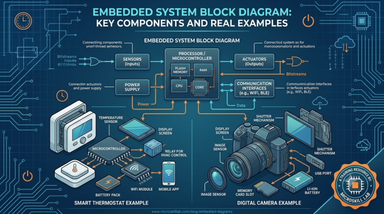
Embedded System Block Diagram Guide for Engineering Students
An embedded system block diagram is a visual map that shows how the input, processor, memory, and output units of a dedicated computing device connect and work together. For engineering students in Bangalore and across India, learning to read and draw this diagram is the first real step toward understanding embedded architecture — before writing a single line of C code. In this guide, we break the block diagram into simple parts using everyday examples like a washing machine and a smart temperature sensor, so the concept sticks.
⚡ Key Takeaways
- You will learn the exact four-block structure used in every embedded system diagram.
- You will see two beginner-friendly examples explained block by block.
- You will understand how signals move from sensor to processor to actuator.
- You will learn the most common diagram mistakes students make in exams and interviews.
- You will get a clear starting point for hands-on practice with real embedded boards.
What Is an Embedded System Block Diagram?
An embedded system block diagram represents the functional flow of a dedicated system using labelled boxes and connecting arrows. Each box stands for a hardware or software block — such as a sensor, microcontroller, or actuator — and the arrows show the direction of data flow between them. Students in Karnataka and Tamil Nadu engineering colleges usually meet this diagram first in their “Embedded Systems” or “Microcontrollers” subject, often before they see any real hardware.
Unlike a general-purpose computer diagram, an embedded block diagram is tightly scoped. It only shows the blocks needed for one dedicated task, which is why the diagrams for a fitness band and a car airbag controller look completely different, even though both are embedded systems.
Most textbooks present the embedded system block diagram as a fixed template, but in practice the diagram changes shape depending on the application. A single-sensor system needs only three or four blocks, while a multi-sensor industrial controller needs separate blocks for each sensor, a signal-conditioning stage, and multiple output actuators. Learning to adapt the basic template to a new problem — rather than memorising one fixed picture — is what separates a strong answer from an average one in university exams.
Why Block Diagrams Matter Before Coding
Drawing the block diagram first forces a student to think about the system as a whole before touching code. It answers three questions: what data comes in, what processing happens, and what output is produced. Skipping this step is one of the biggest reasons beginners get stuck when they open Arduino IDE or Keil for the first time.
Where You Will See This Diagram
You will draw or interpret this diagram in university exams, viva questions, technical interviews at Bangalore hardware firms, and in every project report submitted for embedded electives. Companies hiring for embedded roles in Electronic City and Whitefield often start technical rounds by asking candidates to sketch the block diagram of a system on a whiteboard.
Why Understanding Embedded Architecture Matters for Career Growth
Embedded architecture knowledge is the foundation for every advanced topic that follows — RTOS, device drivers, communication protocols, and PCB design all build on this base. Recruiters at Bangalore-based product companies routinely test whether a fresher can explain how a signal travels from a sensor to an actuator before discussing anything more advanced.
Karnataka’s electronics manufacturing and IT-hardware sector, concentrated around Whitefield and Manyata Tech Park, continues to hire embedded engineers for automotive, industrial automation, and consumer electronics roles. As of 2026, embedded systems engineers in Bangalore with strong architecture fundamentals can expect salaries in the range of ₹4–9 LPA at entry level, moving higher with hands-on project experience.
The Skills Gap Recruiters Notice
Many fresh graduates can recite microcontroller specifications but cannot explain why a particular block diagram uses an ADC before the processor, or why a buffer sits between two blocks. This gap is exactly what our Embedded Systems Pro Programme is designed to close, with practical sessions built around real block-diagram-to-hardware mapping.
Architecture Knowledge Beyond the Exam
Understanding the block diagram also helps students debug faster. When an embedded prototype misbehaves, engineers trace the problem block by block — checking the sensor output, then the processing stage, then the actuator response — rather than guessing at the code randomly.
This block-by-block debugging habit is exactly what separates a fresher from a confident junior engineer in a Bangalore product team. Instead of randomly editing code, an engineer who understands the architecture isolates the faulty block first: is the sensor reading correct, is the value reaching the processor, and is the output stage actually receiving the command? Interviewers often test this reasoning directly by describing a faulty system and asking the candidate to identify which block is likely at fault.
Core Components of an Embedded System Block Diagram
Every embedded system block diagram, regardless of application, is built from four fundamental blocks: input unit, processing unit, memory unit, and output unit. Power supply and communication interfaces are usually added as supporting blocks around this core.
- Input unit — sensors, switches, or transducers that convert a physical quantity (temperature, pressure, light) into an electrical signal
- Processing unit — the microcontroller or microprocessor that runs the embedded software and makes decisions
- Memory unit — RAM for temporary data and ROM/Flash for storing the program permanently
- Output unit — actuators, displays, or motors that convert the processed signal back into a physical action
Supporting Blocks You Should Also Label
Beyond the four core blocks, most real diagrams also include a power supply block, a communication interface block (such as UART, I2C, or SPI), and sometimes a signal conditioning block between the sensor and the processor. Leaving these out is a common reason marks are deducted in university lab exams.
How These Blocks Map to Real Hardware
On an actual development board, the input block might be a push-button or an LDR sensor. The processing block is the microcontroller chip itself, the memory block is built into that same chip, and the output block could be an LED or buzzer. Students who practise on our Electronics Fundamentals programme start by identifying these blocks physically on a breadboard before moving to diagrams on paper.
This physical-to-diagram mapping exercise is one of the fastest ways to make embedded architecture click for a beginner. A student traces current with a multimeter from a sensor pin, through the microcontroller, to an LED. Drawing the same flow as a labelled block diagram then stops feeling abstract. It starts feeling like documentation of something they have already seen work.
- Signal conditioning block — amplifiers or filters placed between a raw sensor and the processor
- Communication interface block — UART, I2C, or SPI modules connecting the processor to other chips or external devices
- Clock/oscillator block — provides timing signals the processor needs to execute instructions in sequence
- Reset circuit block — ensures the processor starts in a known, stable state on power-up
Block Diagram of an Embedded System: Input, Processing, and Output Explained
The simplest way to understand any block diagram of an embedded system is to trace the signal path: input → processing → output. This left-to-right (or top-to-bottom) flow is the backbone of nearly every diagram you will draw as a student.
Step-by-Step Signal Flow
First, the input unit senses a real-world condition and produces a raw electrical signal. Second, this signal often passes through signal conditioning (amplification or filtering) before reaching the processor. Third, the processing unit — guided by the program stored in memory — makes a decision. Finally, the output unit acts on that decision, producing a visible or physical result.
A Simple Comparison: Input Stage vs Output Stage
| Aspect | Input Stage | Output Stage |
|---|---|---|
| Function | Senses physical quantity | Produces physical action |
| Typical components | Sensors, switches, transducers | LEDs, motors, displays, buzzers |
| Signal type | Analog or digital signal in | Analog or digital signal out |
| Example in a washing machine | Water level sensor | Motor driving the drum |
| Common student mistake | Forgetting signal conditioning | Forgetting driver circuit for motors |
Understanding this table helps students avoid drawing an incomplete diagram that jumps directly from sensor to processor without showing the conditioning stage, which examiners in Karnataka technical universities frequently flag.
Simple Examples of Embedded System Block Diagrams
Theory becomes clear only with examples. Here we walk through two beginner-friendly systems that appear often in college assignments and interview questions.
Example 1: Automatic Washing Machine
In an automatic washing machine, the water level sensor and door sensor form the input block. The microcontroller forms the processing block, and the program stored in its internal memory decides the wash cycle. The motor plus water valve form the output block. This is one of the most commonly asked block diagram questions in first-year embedded electives across Tamil Nadu and Karnataka colleges.
Example 2: Smart Temperature Monitoring System
A smart temperature monitoring system uses a temperature sensor as input and a microcontroller as the processing unit. Onboard memory stores the threshold values, and a display plus buzzer form the output — the buzzer sounds if the temperature crosses a set limit. Students building this project in our PIC Microcontroller Programming course learn to map each block to actual PIC microcontroller pins.
Get hands-on with real embedded hardware instead of only drawing diagrams on paper. Our trainers guide you from block-diagram theory to a working prototype using industry-standard tools in Bangalore. Enrol in the Embedded Systems Pro Programme →
Tools Students Use to Build These Examples
- Arduino Uno or PIC16F877A development boards for prototyping
- Breadboards and jumper wires for quick circuit testing
- Proteus or Multisim for simulating the block diagram before building
- A basic multimeter for verifying sensor output at each block
Common Mistakes Students Make While Drawing Block Diagrams
Even strong students lose marks on embedded system block diagrams because of small, repeated errors rather than a lack of understanding. Recognising these mistakes early saves both exam marks and interview confidence.
Mistake 1: Merging Memory Into the Processor Block
Many students draw memory as part of the processor box instead of showing it as a separate labelled block, even though most microcontrollers do have built-in memory. Examiners in Bangalore and Kerala universities usually expect memory to be shown separately to test whether the student understands RAM versus ROM roles.
Mistake 2: Skipping the Power Supply Block
A block diagram without a power supply block is technically incomplete, since every real embedded system needs a regulated voltage source. This is one of the fastest ways to lose a mark in a lab viva, and it is just as easily fixed with practice.
Mistake 3: Confusing Communication Interfaces With Processing Blocks
Some students label I2C or SPI as a processing block rather than a communication interface connecting two separate blocks. This shows a gap in understanding protocol-level architecture — a topic covered in depth in our IoT Programme.
Mistake 4: Drawing Arrows in Only One Direction
Real embedded systems often need feedback — the output stage sends status information back to the processor, such as a motor driver confirming it received a command. Students who draw every arrow pointing left to right miss this feedback loop entirely, which is a common gap in closed-loop system diagrams like a temperature-controlled fan or an automatic door.
Mistake 5: Ignoring the Application Layer in IoT-Based Systems
When the embedded system connects to the internet, such as a smart irrigation controller, the block diagram needs more blocks. It should include the communication module (Wi-Fi or GSM) and, in many cases, a cloud or application layer block. Students preparing for IoT-focused interviews in Bangalore should practise drawing this extended version alongside the classic four-block diagram.
How to Learn Embedded Architecture Hands-On in Bangalore
Reading about block diagrams only takes a student so far — real confidence comes from building the circuit, watching the signal flow, and debugging it when something goes wrong. This is why practical, mentor-led training matters more than textbook memorisation alone.
What a Good Embedded Training Programme Should Cover
- Live circuit building on breadboards, moving from diagram to physical hardware
- Programming practice on Arduino and PIC-based development boards
- Debugging sessions that trace faults block by block, not just line by line
- Capstone projects that combine input, processing, and output blocks into one working system
Getting Started With Us
At Microskill Lab Training Institute, our trainers walk engineering students through the same four-block structure covered in this guide, then move directly into building it on real hardware. Whether you are preparing for university exams, a placement interview, or your final-year project, understanding the embedded system block diagram is the foundation everything else is built on. If you would like a structured, mentor-guided path into embedded architecture, reach out to our team and we will help you choose the right starting course.
Frequently Asked Questions
Q1. What are the four main blocks of an embedded system?
The four main blocks are the input unit, processing unit, memory unit, and output unit, with a power supply block supporting all of them.
Q2. Is a block diagram the same as a circuit diagram?
No. A block diagram shows functional units and signal flow at a high level, while a circuit diagram shows exact components, pin connections, and wiring.
Q3. Do I need to show the power supply block in exams?
Yes. Most university marking schemes in Karnataka and Tamil Nadu expect the power supply block to be shown, and skipping it can cost marks.
Q4. Which examples are best for beginners to practise with?
Simple systems like an automatic washing machine, a digital thermometer, or a traffic light controller are ideal starting points because each block is easy to identify.
Q5. Where can I practise building these systems on real hardware?
You can practise with Arduino or PIC-based development boards, starting with our Arduino Programming course if you are new to embedded hardware.
Q6. How is the block diagram different from the system architecture diagram used in interviews?
In most Bangalore technical interviews, the two terms are used interchangeably for entry-level roles. A formal architecture diagram sometimes adds more detail on top of the basic block diagram structure, such as bus widths and specific chip part numbers.