
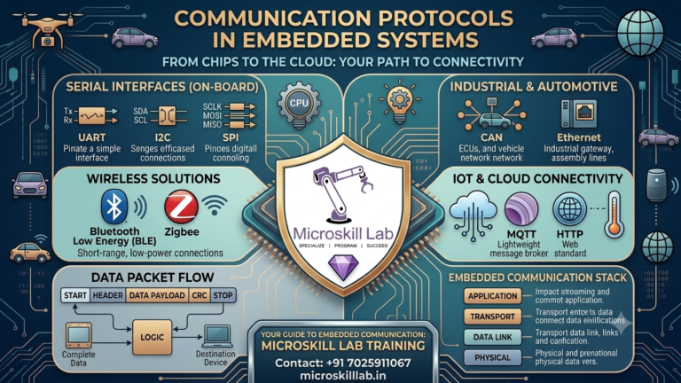
Communication Protocols in Embedded Systems: UART, SPI, I2C & CAN
Communication protocols in embedded systems are the rules that let a microcontroller talk to sensors, memory chips, displays, and other boards. Every embedded design student in Bangalore and across India runs into UART, SPI, I2C, and CAN within the first few weeks of hands-on training. This guide breaks down each protocol in plain language, compares their speed and wiring, and shows where they fit into real embedded design projects.
Understanding these four protocols is not optional for anyone serious about an embedded systems career. Datasheets for almost every microcontroller, sensor, or module reference at least one of them. Lab exercises across engineering colleges in Karnataka, Kerala, Tamil Nadu, Telangana, and Andhra Pradesh build directly on this foundation.
By the end of this guide, you will recognise which protocol a component uses simply by reading its pinout.
⚡ Key Takeaways
- You will learn how UART, SPI, I2C, and CAN differ in wiring, speed, and use cases.
- You will understand which protocol suits sensor interfacing, memory access, or automotive design.
- You will see a side-by-side comparison table to revise before interviews.
- You will get practical tips our trainers use when teaching embedded design in Bangalore.
- You will learn how these protocols connect to real IoT and automotive embedded systems roles.
What Are Communication Protocols in Embedded Systems?
Communication protocols in embedded systems define how two or more digital devices exchange data reliably. Without a shared protocol, a microcontroller and a sensor would send electrical signals that neither side could interpret correctly. Our trainers introduce this concept early because every embedded design project, from a simple temperature logger to a connected IoT gateway, depends on it.
A protocol specifies far more than just wiring. It defines voltage levels, timing, how a frame of data starts and ends, and how errors are detected and handled. Two chips can be physically wired correctly and still fail to communicate if their protocol settings, such as baud rate or clock polarity, do not match.
This is why our lab sessions spend as much time on protocol configuration as on the wiring itself.
Serial vs Parallel Communication
Most embedded communication protocols are serial, meaning data travels one bit at a time over a single wire or wire pair. Parallel communication moves multiple bits at once but needs more pins and is rarely used in modern embedded design. Bangalore’s IT and electronics sector, including firms around Electronic City and Whitefield, favours serial protocols because they reduce board space and cost.
Synchronous vs Asynchronous Protocols
Synchronous protocols like SPI and I2C share a clock signal between devices, so data transfer stays tightly timed. Asynchronous protocols like UART have no shared clock and instead agree on a fixed data rate in advance. Students preparing for embedded systems interviews should be able to explain this distinction clearly, since it comes up often in campus placement rounds across Karnataka.
Why Communication Protocols Matter for Embedded Design Careers in Bangalore
Karnataka’s electronics and semiconductor sector has grown steadily, and firms near Manyata Tech Park and Electronic City regularly hire engineers who understand hardware-level communication. Recruiters expect embedded design candidates to explain protocol selection, not just recite definitions. This is a core reason our Embedded Systems Pro Programme dedicates full lab sessions to each protocol.
Beyond product companies, Bangalore’s growing base of IoT startups, industrial automation firms, and automotive Tier-1 suppliers all rely on engineers who can move confidently between UART, SPI, I2C, and CAN. A student who explains why a design team chose one protocol over another shows the practical judgement that separates a strong fresher from an average one during technical rounds.
Where Employers Test Protocol Knowledge
Technical interviews at product companies and automotive suppliers in Bangalore frequently include protocol-comparison questions, waveform-reading exercises, and debugging scenarios. Freshers who can trace a logic analyser capture of an I2C transaction stand out immediately. This practical skill is difficult to build from theory alone, which is why lab time matters.
Salary Context for Protocol-Skilled Engineers
Embedded engineers comfortable with UART, SPI, I2C, and CAN generally command stronger starting offers than candidates without hands-on protocol experience. Exact figures vary by company and role and should always be verified against current market data before publishing.
UART: The Simplest Serial Communication Protocol
UART, or Universal Asynchronous Receiver-Transmitter, is usually the first protocol students in embedded design courses learn. It uses just two wires, TX and RX, making it easy to wire and debug on a breadboard. Our Electronics Fundamentals course uses UART to introduce the idea of framed serial data.
Because UART needs no shared clock line, it is often the easiest protocol for beginners to wire correctly on their first attempt. Many students in our labs build their first working serial link with UART before moving on to the more involved timing requirements of SPI and I2C.
How UART Frames Data
A UART frame starts with a start bit, carries 5 to 9 data bits, an optional parity bit, and ends with one or more stop bits. Both devices must agree on the baud rate in advance since there is no shared clock line. Common baud rates in embedded design include 9600, 115200, and 250000 bits per second.
If the baud rate on either side is even slightly mismatched, the receiving device misreads bit boundaries and the data arrives as garbage characters. This is one of the first debugging exercises we set for students, since it teaches careful attention to datasheet specifications rather than guesswork.
Typical UART Use Cases
UART remains popular for simple point-to-point links such as GPS modules, Bluetooth modules, and debug consoles on development boards.
- Serial debug output during firmware development
- GPS module data streaming
- Bluetooth and GSM module communication
- PC-to-microcontroller programming interfaces
SPI in Embedded Systems: High-Speed Synchronous Communication
SPI, or Serial Peripheral Interface, is a synchronous protocol built for speed. It uses four lines: MOSI, MISO, SCLK, and a chip-select line per device. Students on our PIC Microcontroller Programming course use SPI extensively when interfacing displays and memory chips.
SPI in embedded systems is prized for its simplicity at the protocol level, even though its wiring grows quickly with each added device. There is no addressing scheme to configure and no acknowledgement bit to manage, which keeps the underlying logic straightforward once students understand the four core signal lines.
SPI Wiring and Master-Slave Roles
One master device controls the clock and selects which slave to talk to using individual chip-select lines. This full-duplex design lets SPI transfer data far faster than UART or I2C, often exceeding several megabits per second. The trade-off is more wiring, since each additional slave device needs its own chip-select pin.
Clock polarity and clock phase settings, commonly called CPOL and CPHA, must match between master and slave for reliable transfer. Students learn to check these four SPI modes against a component’s datasheet before writing any driver code, since mismatched settings are a frequent source of silent communication failures.
Where SPI Fits in Embedded Design
SPI in embedded systems is the default choice whenever high throughput matters more than pin count. Common applications include SD card interfacing, TFT display driving, and external flash memory access.
- SD card and external flash memory interfacing
- TFT and OLED display driving
- High-speed ADC and DAC communication
- Sensor arrays needing fast, repeated polling
SPI vs I2C vs UART vs CAN: Quick Comparison
| Feature | UART | SPI | I2C | CAN |
|---|---|---|---|---|
| Wires needed | 2 | 4 (+1 per slave) | 2 | 2 |
| Communication type | Asynchronous | Synchronous | Synchronous | Asynchronous, message-based |
| Typical speed | Up to 1 Mbps | Several Mbps | Up to 3.4 Mbps | Up to 1 Mbps |
| Devices supported | Point-to-point | Multiple slaves | Multiple devices (addressed) | Multiple nodes (bus) |
| Common use in embedded design | Debug, GPS, Bluetooth | Displays, memory, sensors | EEPROM, RTC, sensor hubs | Automotive, industrial control |
I2C in Embedded Systems: Multi-Device Communication Made Simple
I2C, or Inter-Integrated Circuit, uses only two wires, SDA and SCL, yet supports dozens of devices on the same bus through unique addressing. This makes I2C in embedded systems a favourite for sensor-heavy designs where board space is limited. Our IoT Programme covers I2C in depth for connecting multiple environmental sensors to one controller.
I2C was originally developed for short-distance, chip-to-chip communication on a single circuit board, and that heritage still shapes how it is used today. Real-time clocks, EEPROMs, and small sensor modules almost always default to I2C because it keeps pin count low on compact embedded design boards.
How I2C Addressing Works
Every device on an I2C bus has a 7-bit or 10-bit address, and the master initiates communication by sending that address before any data. Pull-up resistors on SDA and SCL are required since I2C uses open-drain outputs. Address conflicts are a common debugging challenge students face during lab sessions.
Some sensor modules allow the last address bit or two to be set with a solder jumper or pin strap, which lets designers place multiple identical sensors on one bus. Students practise this technique when building multi-sensor environmental monitoring boards in our IoT labs.
I2C Strengths and Limitations
I2C trades speed for simplicity and pin savings, making it ideal for low-frequency sensor reads rather than high-bandwidth data transfer. Its shared bus also means only one device can communicate at a time, which can create bottlenecks in complex embedded design projects.
Get hands-on with UART, SPI, I2C, and CAN on real development boards under expert guidance. Our trainers walk you through every protocol with live wiring and debugging sessions. Enrol in our Embedded Systems Pro Programme →
CAN Protocol: Communication Backbone of Automotive Embedded Design
CAN, or Controller Area Network, was built for reliability in electrically noisy environments like vehicles and industrial machinery. Unlike UART, SPI, and I2C, CAN is message-based rather than address-based, and every node on the bus can see every message. Bangalore’s automotive and industrial embedded design sector relies heavily on CAN for body control, powertrain, and infotainment modules.
CAN was originally developed for automotive wiring harnesses, where reducing the number of point-to-point connections between electronic control units delivers major cost and weight savings. That same advantage now extends to industrial automation panels and factory floor equipment across Karnataka’s manufacturing belt.
CAN Bus Architecture
A CAN bus uses two wires, CAN-H and CAN-L, in a differential signalling scheme that resists electrical noise far better than single-ended protocols. Multiple nodes connect to the same bus, and message priority is resolved automatically through bit-level arbitration rather than a central master device.
Each CAN message carries an identifier that doubles as its priority level, so lower-numbered identifiers win arbitration and transmit first whenever two nodes try to send at the same time. This built-in prioritisation is central to how safety-critical automotive embedded systems guarantee that urgent messages, such as brake signals, are never delayed by less important traffic.
Why CAN Suits Automotive Embedded Systems
Automotive and industrial embedded systems demand fault tolerance, and CAN’s built-in error detection and arbitration make it well suited to environments with long cable runs and electrical interference. Students interested in automotive embedded design should pair CAN knowledge with our Embedded Linux Development course to understand how CAN data reaches higher-level applications.
How to Choose the Right Communication Protocol for Your Embedded Design
Choosing between UART, SPI, I2C, and CAN depends on speed requirements, wiring constraints, number of connected devices, and the electrical environment of the final product. Our PCB Designing course teaches students to make these trade-offs at the schematic stage, before a single line of firmware is written.
Protocol choice also affects cost. Extra chip-select lines for SPI can push a design toward a larger, pricier microcontroller, while a CAN transceiver adds bill-of-materials cost that only makes sense in noisy or safety-critical environments. Weighing these trade-offs early prevents expensive redesigns later in the embedded design process.
A Practical Decision Framework
Start by asking how many devices need to communicate and whether the link is point-to-point or shared across many nodes. Then weigh speed needs against available pins, since SPI’s extra chip-select wires can quickly consume GPIO on smaller microcontrollers.
- Point-to-point, low pin count, moderate speed: choose UART
- High-speed, few devices, extra pins available: choose SPI
- Many low-speed devices, minimal wiring: choose I2C
- Noisy environment, many nodes, safety-critical: choose CAN
Building Protocol Fluency Through Practice
Reading protocol datasheets is not enough; students need to capture real waveforms on a logic analyser and debug timing issues themselves. This hands-on approach is central to how we structure lab work across every embedded design course at our institute, preparing students for the practical questions Bangalore employers actually ask.
Frequently Asked Questions
What is the main difference between SPI and I2C in embedded systems?
SPI uses four wires and a dedicated chip-select line per device, giving higher speed at the cost of more pins. I2C uses just two wires with device addressing, saving pins but running slower.
Is UART still relevant in modern embedded design?
Yes. UART remains common for debug consoles, GPS modules, and simple point-to-point links where speed is not the priority.
Why does automotive embedded design use CAN instead of I2C or SPI?
CAN’s differential signalling and built-in error detection handle electrical noise and long cable runs far better than I2C or SPI, which is essential in vehicles.
Can one microcontroller use multiple communication protocols at once?
Yes. Most modern microcontrollers include separate UART, SPI, and I2C peripherals, allowing a single embedded design to use all three simultaneously for different tasks.
Where can I practice these protocols hands-on in Bangalore?
Our Contact Us page has details on lab-based embedded design training covering UART, SPI, I2C, and CAN with real development boards.