
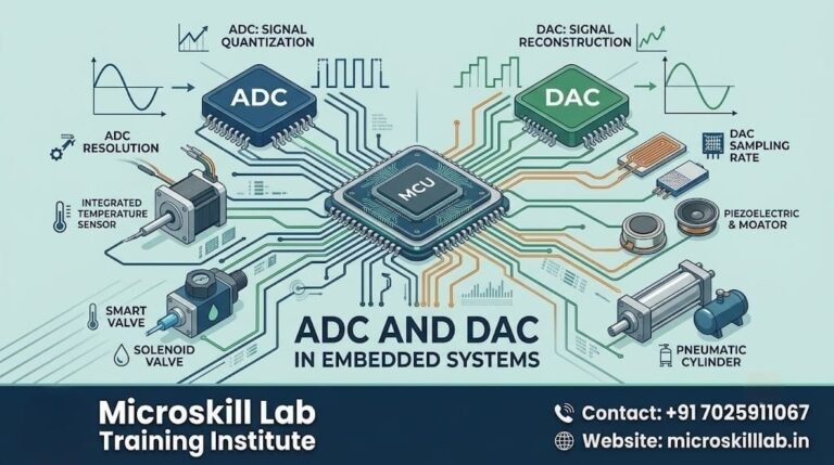
ADC and DAC are the two converters that let an embedded system talk to the real world. An analog to digital converter (ADC) turns continuous signals like temperature or sound into numbers a microcontroller can process, while a digital to analog converter (DAC) turns those numbers back into smooth analog output such as audio or motor control voltage. If you are an ECE, EEE, or CSE fresher in Bangalore learning embedded hardware, mastering these two blocks is your first real step from theory into working projects. This guide breaks down how they work, where they sit inside ARM microcontrollers, and how our trainers teach them through live sensor projects.
⚡ Key Takeaways
- You will understand what ADC and DAC do and why every embedded system needs them to bridge the analog and digital worlds.
- You will learn how resolution, sampling rate, and reference voltage decide the accuracy of your sensor readings.
- You will see how ADC and DAC peripherals are built into common ARM microcontrollers used across Bangalore’s electronics industry.
- You will gain clarity on real applications, from audio playback to motor control, that hiring companies expect freshers to grasp.
- You will discover how our hands-on curriculum turns these concepts into portfolio-ready projects.
What Are ADC and DAC in Embedded Systems?
An analog to digital converter samples a real-world signal at fixed intervals and assigns each sample a numeric value. That value is what your microcontroller code actually reads and acts on. Without an ADC, a temperature sensor or microphone would produce a voltage your processor simply cannot interpret.
A digital to analog converter does the reverse job. It takes a stream of digital values from your program and rebuilds a smooth, continuous voltage. This is how an embedded board plays audio through a speaker or sets a precise control voltage for an actuator.
The Analog and Digital Divide
The physical world is analog, meaning signals vary continuously and can take infinite values. Computers are digital and work only with discrete numbers, usually binary. ADC and DAC are the translators that sit between these two domains inside every modern device.
For a beginner, the cleanest mental model is a bridge. Sensors feed analog data across the ADC bridge into your code, and the DAC bridge carries processed results back out to the physical world. Our trainers use this bridge model in the first week of our Embedded Systems Pro Programme to anchor everything that follows.
Why Beginners Must Learn Both
Many freshers in Karnataka focus only on writing code and skip the signal side entirely. That gap shows up fast in interviews at product companies in Electronic City and Whitefield. Recruiters at embedded firms routinely ask candidates to explain resolution and sampling, so a clear grasp of both converters gives you a genuine edge.
How an Analog to Digital Converter Works
An ADC performs two core operations, sampling and quantization. Sampling captures the signal value at regular time steps, and quantization maps each captured value to the nearest available digital level. Together these decide how faithfully your digital copy matches the original signal.
The number of available levels depends on the converter’s bit depth. An 8-bit ADC offers 256 levels, while a 12-bit ADC offers 4,096, giving much finer detail. Most ARM Cortex-M microcontrollers used in our labs ship with 12-bit ADCs as standard.
Resolution, Sampling Rate, and Reference Voltage
Resolution is the smallest voltage change an ADC can detect, set by bit depth and reference voltage. A higher reference voltage spread across the same bits means each step covers more voltage, reducing fine detail. Choosing the right reference is a practical skill our trainers drill through real sensor wiring.
Sampling rate is how many samples the converter takes per second. The Nyquist rule says you must sample at least twice the highest signal frequency to capture it correctly. Getting this wrong produces aliasing, a distortion beginners often meet when reading audio or vibration data.
Common ADC Types You Will Meet
Successive approximation ADCs are the most common in microcontrollers because they balance speed and cost well. Sigma-delta ADCs give very high resolution for slow signals like temperature and weight. Flash ADCs are extremely fast but expensive, used mainly in specialised instrumentation.
Understanding which type suits which job is exactly the kind of applied knowledge covered in our Electronics Fundamentals course. We map each converter type to concrete Bangalore industry use cases so the theory sticks.
How a Digital to Analog Converter Works
A DAC receives a digital number and produces a proportional analog voltage at its output pin. It effectively reverses quantization, rebuilding voltage steps that approximate the intended smooth waveform. A following low-pass filter then smooths those steps into a clean signal.
The quality of DAC output again depends on bit depth. A higher-resolution DAC produces finer voltage steps and therefore smoother audio or control signals. Beginners see this vividly when comparing an 8-bit and a 12-bit DAC driving the same speaker.
Resistor Ladders and PWM Alternatives
Many DACs use an R-2R resistor ladder network to convert bits into weighted voltages accurately. This design is compact and features in several ARM chips our students program. It is worth studying because it explains why higher bit counts cost more silicon.
Smaller microcontrollers without a true DAC often fake analog output using pulse width modulation. PWM rapidly switches a pin on and off, and a filter averages it into a variable voltage. Our curriculum contrasts real DAC output with the PWM approach so learners choose correctly on real boards.
Real Output Applications
DACs drive audio amplifiers, generate control voltages for motors, and produce reference levels for test equipment. In robotics projects at our lab, students use a DAC to set precise motor speed rather than crude on-off control. This hands-on contrast makes the concept memorable and interview-ready.
ADC and DAC Inside ARM Microcontrollers
Modern ARM Cortex-M chips integrate ADC and often DAC peripherals directly on the silicon. This on-chip integration removes the need for external converter ICs in most beginner and intermediate projects. It also keeps board designs compact, which product companies across Bangalore value heavily.
Accessing these peripherals means configuring registers or using a vendor library such as STM32 HAL. Our trainers teach both the register-level view and the library approach so students understand what happens underneath. That depth is what separates a confident engineer from someone who only copies example code.
Popular Chips Used in Industry
STM32 microcontrollers from STMicroelectronics dominate many Indian embedded product designs. Their built-in 12-bit ADC and DAC make them ideal teaching platforms for converter concepts. We standardise several of our lab exercises on STM32 boards for exactly this reason.
Beginners also meet ADC peripherals on ESP32 and various Arduino-compatible boards. Learning to read a datasheet and locate ADC channels is a core skill in itself. Our ARM microcontroller training builds that habit systematically from the very first lab.
Reading the Datasheet Correctly
A datasheet lists ADC resolution, channel count, maximum sampling rate, and reference options. Freshers often overlook input impedance and settling time, which quietly wreck accuracy. Our trainers walk each student through a real STM32 datasheet page by page until it feels familiar.
This datasheet fluency matters directly for employability in Karnataka’s product sector. Companies in Manyata Tech Park expect a fresher to interpret converter specs without hand-holding. Building that habit early is a deliberate part of our teaching approach.
Get hands-on with real ADC and DAC circuits on ARM boards, guided by trainers with genuine industry experience. Our project-based labs take you from first sensor reading to a working converter application. Explore the Embedded Systems Pro Programme →
Real-World Applications Beginners Should Know
ADC and DAC appear together in almost every embedded product you use daily. A digital thermostat reads temperature through an ADC and may drive a display or actuator through further conversion. Recognising this pattern helps beginners see the converters as a system, not isolated parts.
Signal processing pipelines rely on this pair constantly. Audio devices digitise sound with an ADC, process it in software, then reconstruct it with a DAC for playback. Understanding this full loop is essential for anyone targeting audio or instrumentation roles.
Sensors and Data Acquisition
Most sensors output an analog voltage proportional to what they measure. An ADC turns that voltage into readable data for logging, display, or control decisions. Data acquisition systems in Bangalore’s manufacturing sector depend on exactly this chain.
Our students build a live data acquisition project using real sensors and an ARM board. They wire the sensor, configure the ADC, and plot readings, closing the gap between theory and practice. This capstone-style exercise is one graduates cite most often in interviews.
Audio, Motor Control, and IoT
In IoT nodes, an ADC reads environmental sensors before data is sent to the cloud. A DAC or PWM output then drives local actuators based on decisions or commands. This sense-process-actuate loop underpins our IoT Programme projects.
Motor control uses converters to set speed and torque smoothly rather than abruptly. Audio applications use them to capture and reproduce sound faithfully. Seeing one converter concept serve so many domains is what makes the topic genuinely exciting for beginners.
ADC vs DAC: A Clear Comparison
Beginners often blur the two converters because they sound similar and work as a pair. The table below sets out the practical differences our trainers emphasise in class. Keeping these distinctions clear prevents common exam and interview mistakes.
Side-by-Side Differences
The direction of conversion is the single most important difference to remember. An ADC moves signals from analog into digital, and a DAC moves them from digital back to analog. Everything else follows from that basic direction of data flow.
Table: ADC vs DAC at a Glance
| Feature | ADC (Analog to Digital) | DAC (Digital to Analog) |
|---|---|---|
| Input | Continuous analog voltage | Discrete digital value |
| Output | Digital number | Continuous analog voltage |
| Core operation | Sampling and quantization | Reconstruction and filtering |
| Typical use | Reading sensors | Driving audio or actuators |
| Common on-chip type | Successive approximation | R-2R resistor ladder |
| Beginner project | Temperature logger | Audio tone generator |
Choosing the Right Converter Specs
For any project, start by asking what signal you must read or produce. Match the converter’s resolution and speed to the signal, not to the highest number on the datasheet. Over-specifying wastes cost and power, a lesson our trainers reinforce on every lab build.
Building Your Embedded Skills at Microskill Lab
Learning ADC and DAC properly takes structured guidance and real hardware, not just videos. Our Bangalore-based training combines clear theory with lab time on ARM boards from the very first week. Learners across Karnataka, Kerala, Tamil Nadu, Telangana, Andhra Pradesh, and Pondicherry join us to build exactly this foundation.
Embedded roles in India reward practical converter skills strongly. Entry-level embedded engineers in Bangalore earn an indicative ₹4–8 LPA, with experienced signal-processing specialists reaching higher. These figures are broad ranges and worth verifying against current job listings before you rely on them.
What Makes Our Approach Different
We teach converters through projects rather than slides alone. Every concept in this guide maps to a lab exercise a student wires and tests personally. That experience is what turns a nervous fresher into a confident interviewee.
Our trainers bring real embedded industry background to each session. They connect converter theory to the actual boards and problems Bangalore product companies work with daily. This lived context is the heart of our teaching quality.
Start Your Embedded Journey
If you are ready to move from theory to working hardware, structured training accelerates you dramatically. You gain mentorship, real boards, and a project portfolio that speaks in interviews. Reach out through our enquiry page to discuss the right starting course for your background.
The demand for embedded talent across South India continues to grow steadily. Mastering foundational blocks like ADC and DAC positions you well for that demand. Your journey from beginner to embedded engineer can begin with a single well-taught concept.
Frequently Asked Questions
What is the difference between ADC and DAC?
An ADC converts a continuous analog signal, such as a sensor voltage, into a digital number your microcontroller can process. A DAC does the opposite, turning digital values into a smooth analog voltage for output. They frequently work together in a single embedded system.
Do all microcontrollers have a built-in DAC?
No, many low-cost microcontrollers include an ADC but lack a true DAC. These chips often approximate analog output using pulse width modulation and an external filter instead. ARM chips like several STM32 models do include real on-chip DACs.
What ADC resolution do beginners need?
For most beginner sensor projects, a 10-bit or 12-bit ADC is more than sufficient. The 12-bit ADC found on common ARM boards gives good accuracy without added complexity. You only need higher resolution for precision instrumentation work.
Why is sampling rate important in an ADC?
Sampling rate determines the highest signal frequency you can capture accurately. The Nyquist rule requires sampling at least twice the signal’s top frequency. Sampling too slowly causes aliasing, which distorts your data noticeably.